2016年4月20日星期三

ARCH 653 Project 2 Visual Programming of Superdome Stadium

Project 2 is the extension of previous Superdome Stadium model in Revit.  The major concern is to improve the stadium interior design and structural design by using Dynamo.


There are two major parts in this project. The first is to color the seats inside of the stadium. Then the body frame is created based on the actual structural frame which include the surface frame and vertical truss are finished by using Dynamo. 

1. Seating colors

There are three different layers of seats in the stadium as the figures below.  Level 1 and Level 2 seats models are created by using four curve units and level 3 seats model is made up of two semicircle units. The coloring process will based on these model units.


Because Superdome Stadium is mainly used as for New Orleans Saints home games, using color of seats to reveal the team name and the city name is a good idea. For Level1 and Level2 seats, I change the color by override a image. The pictures below show the color and dynamo program. The selected surface is divided into sets of points based on the given U and V value. Then the color image is also divided into pixels which corresponding the surface. Next, using "adaptive component by point" and "Override color in View" to change the panels color based on image.


For the seats in level 3, I use a different Dynamo code to render the seating colors. It is a method that import data from Excel sheet. Different from the previous levels, this model is editted in the mass family. Firstly, I create three colors, black and old gold from the football team primary color, white is the third one. Then, an spread sheet is created and showed in below. Three numbers represent three colors. After that, the dynamo code is create to link the numbers in sheet to the color in the menu. Finally, using the "SetParameterByName" to assign the color to each seat. The result shows a chessboard color arrangement.


2. Surface frame and vertical truss.

In the second part, I focus on the structural elements for this model. Although a frame was created in the project1, that was just a general configuration and the frame and surface were separated. I optimize the structure desgin by using dynamo. Pictures below show the actual structure of Superdome and my thought 
about the structure.


First I create the surface frame and surface panel. The Dynamo program for these two are similar. The first thing to do is to select the curve lines of the mass model and use them to create a polycurve. Then, using the "UV Quad On Surface" node to create points on the surface. After that, assigning the materials to the surface according to the points we have. 
This method can be used for both surface frames and surface panels, but one thing need to be careful is the location about panels and frames. We don't want to them overlap together. So when I create the panel family, I move it slightly above the plane and the height is the same of frame thickness. In this way, we can create a panel that "paved" on the frame.


The next part is to create the vertical truss that supporting the surface frames and panels. Two different types of truss are used, one is the triangular truss and another is the main column. The mechanism of this Dynamo code is to 1) selecting face and edge of the model, 2) creating cutting plane on the selected and use them cut the surface, 3) choosing certain points on the cutting curve, 4) assigning adaptive family to those points. 
 
After all the individual Dynamo files are finished, they are applied to one model project. The following pictures shows the process.


2016年3月8日星期二

ARCH 653: Building Information Modeling, Yunkun

Project 1 : Parametric Design

Superdome in New Orleans, Louisiana

1. Stadium Introduction

The San Francisco 49ers play the Baltimore Ravens in Super Bowl XLVII at the Superdome in New Orleans on Sunday.
Photo source: Charlie Riedel


Source:https://www.fema.gov/media-library/assets/images/53562#details

The Mercedes-Benz Superdome is the world’s largest fixed dome structure construction located in New Orleans, Louisiana. It is regard as one of the state’s most recognizable landmark. This stadium was completed in 1975 and designed by the New Orleans modernist architectural firm of Curtis and Davis. Its steel frame covers 13 acre expanse and the dome is supported by a lamellar multi-ringed frame which is 680 feet. This stadium was renovated in 2005 after hitting by Katrina and two sections of superdome roof were blow away. It is now served as the major venue for events in sport, entertainment and politics and also used as the stadium for New Orleans Saints.


Facts About the Superdome
  • Land space: 52 acres (210,000 square meters) 
  • Area of roof: 9.7 acres (440,000 square feet) 
  • Height: 273 feet (82.3 meters) 
  • Dome diameter: of 680 feet (210 meters) 
  • Main arena floor: 162,434 square feet 
  • Maximum seating: 73,208 
  • UBU™ synthetic turf: 60,000 square feet 
  • Construction cost (1971-1975): $134 million 
  • Post-Katrina renovations and enhancements: $336 million 
  • Host of more Super Bowls than any other stadium: XII, XV, XX, XXIV, XXXI, XXXVI, and XLVII 

2. Parametric Modeling


The building mass of this stadium is not complicate. It can be divided into five levels and controlled by 11 levels. The ground level of this building is just few simple extrusions. I will skip of this part and start with the building entrance.


The entrance and the base were created by the similar shape. It consist of four arcs whose intersection points were defined by a square. The width of these arcs and radius of arcs were define by parameters. Then, the forms were created between them. Then, the base top was by forming a surface and a void circle.


Next step is to build the dome body. Two lines and one small arc were used to describe the configuration of the stadium. They were aligned to five levels to control the height of each part. Three different radius were assigned to control the width of the body.


In the end, the dome was created by letting an arc revolve through a center line. It was similar to the body. The height was defined by distance between levels; width was controlled by radius. 


2. Facade and Frame


The facade panel of this building is shown as the picture above. It is attached on the stadium body and base walls. Most of the panels are rectangle shape, but the center part of body has a arc surface. normal rectangle panels are unable to show arc surface. the panel with convex in the center will have gap between panels. 


The structure of this stadium was also built by mass family. The method was the same with building facade panels. But the panel families were designed as frame shape to mimic the real frame structure.


In addition, the parameters in the frame family were defined in the same way with the building mass. After the frame family are loaded into building mass. Their location were controlled by linking these parameters from different families.

3.Mass to Project


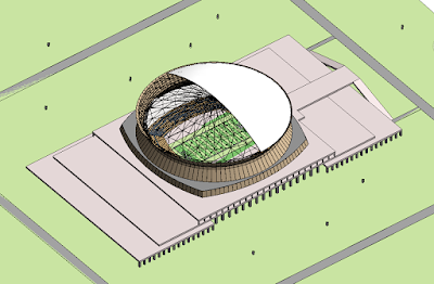
After all the families has been finished. They were load to one project. Beside that, I also created a seats and downloaded a football flied family to make it looks better. Because this file is a little large. So I only create the lowest level of seats. Other elements like site, structure columns were added too.

Here are some rendering pictures.